| Items |

P620F-33
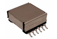
9 Ampere (A) Secondary Output Current P620F Series Flyback Transformer
|

P620F-50
6 Ampere (A) Secondary Output Current P620F Series Flyback Transformer
|

P620F-12
2.50 Ampere (A) Secondary Output Current P620F Series Flyback Transformer
|

P620F-19
1.50 Ampere (A) Secondary Output Current P620F Series Flyback Transformer
|

P620F-24
1.25 Ampere (A) Secondary Output Current P620F Series Flyback Transformer
|
|
Power
|
N/A
30 W
|
|
Primary OCL (±10%)
|
N/A
42 µH
|
|
Maximum Primary Direct Current Resistance (DCR)
|
N/A
0.070 mOhm
|
N/A
0.069 mOhm
|
N/A
0.061 mOhm
|
N/A
0.060 mOhm
|
N/A
0.060 mOhm
|
|
Maximum Secondary Direct Current Resistance (DCR)
|
N/A
0.0023 mOhm
|
N/A
0.0050 mOhm
|
N/A
0.0150 mOhm
|
N/A
0.0370 mOhm
|
N/A
0.0550 mOhm
|
|
Maximum Auxiliary Direct Current Resistance (DCR)
|
N/A
0.220 mOhm
|
N/A
0.225 mOhm
|
N/A
0.195 mOhm
|
N/A
0.195 mOhm
|
N/A
0.195 mOhm
|
|
Maximum Primary Inductance LL
|
N/A
3.00 µH
|
N/A
1.60 µH
|
N/A
0.55 µH
|
N/A
0.43 µH
|
N/A
0.31 µH
|
|
Primary : Secondary Turns Ratio (±5 %)
|
N/A
1 : 0.09
|
N/A
1 : 0.14
|
N/A
1 : 0.33
|
N/A
1 : 0.56
|
N/A
1 : 0.67
|
|
Primary : Auxiliary Turns Ratio (±5 %)
|
N/A
1 : 0.33
|
|
Secondary Output Voltage
|
N/A
3.3 V
|
N/A
5.0 V
|
N/A
12 V
|
N/A
19.5 V
|
N/A
24 V
|
|
Secondary Output Current
|
N/A
9 A
|
N/A
6 A
|
N/A
2.50 A
|
N/A
1.50 A
|
N/A
1.25 A
|
|
Industry Standards / Certifications
|
N/A
RoHS Compliant
|
|
Isolation RMS Voltage (Vrms)
|
N/A
1500 V
|
|
Isolation Time
|
N/A
60 s
|
|
Operating Frequency
|
N/A
250 kHz
|
|
Standard Operating Temperature Range
|
N/A
-40 to +125 ºC
|
|
Available Design
|
N/A
Custom
|
|
Note
|
N/A
- Primary OCL measured at 250 kHz 0.7 Vrms
- Primary Leakage L measured at 250 kHz 0.7 Vrms with 7-8-9-10-11-12 shorted
- DCR measured with windings in parallel
- Hipot: 1500 Vrms, 1 mA, 60 s (Primary, Auxiliary to Secondary); 1800 Vrms, 1 mA, 5 s (Primary, Auxiliary, and Core to Secondary); 500 Vrms, 1 mA, 5 s (between Primary, Auxiliary, and Core) Polarity: 1, 2, 5, 10, 11, and 12 are in phase
- Ipk: 2.6 Adc, Δ L < 10% from initial value
Product performance is limited to specified parameters. Data is subject to change without prior notice.
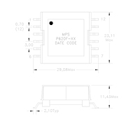
Dimensions
Unless otherwise specified, all tolerances are:
inch: .XX : ±0.010 .XXX : ±0.005
mm: X.X : ±0.254 X.XX : ±0.13
|


